
Ultrasonic Coating of PEM Electrolyte Anode Catalyst Layer
Application and Key Technologies of Ultrasonic Coating in the Preparation of PEM Electrolyte Anode Catalyst Layers
Ultrasonic coating technology is one of the core technologies for the large-scale preparation of PEM electrolyte anode catalyst layers. Through the ultrasonic cavitation effect and precise process control, it solves the pain points of traditional coatings, such as poor uniformity, low catalyst utilization, and high consumption of precious metals. Simultaneously, it is compatible with composite catalyst layer structure design, providing support for the mass production of low-load, high-performance, and long-life anode catalyst layers.
Core Positioning and Value
The core objectives of ultrasonic coating in the preparation of anode catalyst layers for PEM electrolyzers are cost reduction, efficiency improvement, and performance stabilization, specifically reflected in three aspects:
1. Reduced Dependence on Precious Metals: By precisely controlling the coating amount of iridium-based catalysts (which can be reduced to 0.1~0.7 mg/cm², far lower than the traditional >1 mg/cm²), combined with non-precious metal catalyst composite design, the scalability bottleneck caused by the scarcity of iridium resources is alleviated;
2. Enhanced Catalytic Performance: Optimizing the proton/electron conduction and gas-liquid mass transfer pathways of the anode catalyst layer, achieving low overpotential at high current densities (e.g., with an iridium loading of 0.5 mg/cm², the current density can reach 4 A/cm² at 2V);
3. Ensuring Mass Production Stability: Solving problems such as excessively thick edges and coating defects in traditional spraying, meeting the consistency requirements of membrane electrode assemblies (MEAs) for gigawatt-scale PEM electrolyzers.

Key Technical Features
Ultrasonic coating, leveraging the unique properties of ultrasound, exhibits irreplaceable advantages in anode catalyst layer preparation:
1. Ultra-high coating uniformity: Utilizing the cavitation effect of ultrasound, the catalyst slurry is atomized into uniform droplets, achieving a coating uniformity of ±5%, avoiding edge thickness deviations common in traditional spraying (solving the problem of performance degradation at the edges of the membrane electrode);
2. Precise parameter controllability: Coating thickness (e.g., 20~200nm for non-precious metal layers, 4~8μm for precious metal layers) and catalyst loading (as low as 0.01mg/cm²) can be precisely adjusted to adapt to different anode catalyst layer structure designs;
3. Low defects and high adhesion: Ultrasonic vibration reduces defects such as bubbles and cracks in the coating, while enhancing the adhesion between the catalyst and the substrate (membrane or PTL), preventing coating cracking or peeling under high current densities;
4. High material utilization rate: Raw material utilization can reach 95%, reducing catalyst slurry consumption by more than 50% by reducing over-spraying, significantly lowering precious metal costs;
5. Anti-swelling design: Equipped with a vacuum heating system, the proton exchange membrane (PEM) can be fixed and its swelling controlled, preventing membrane deformation during coating from affecting the catalyst layer structure.
Typical Preparation Process and Key Parameters
Ultrasonic coating requires a synergistic design considering the structure of the anode catalyst layer (single or composite), slurry formulation, and process steps. Typical processes and parameters are as follows:
1. Slurry Preparation (Anode-Specific)
The anode catalyst slurry needs to be suitable for highly acidic (pH≈0) and highly oxidizing (>1.3V) environments. The formulation is divided into two categories:
- Non-precious metal slurry (bottom layer of composite layer): Non-precious metal catalyst (two-dimensional transition metal sulfides/oxides/nitrides, such as MoS₂, VOₓ, etc.), ionomer solution (5~20wt% perfluorosulfonic acid resin), deionized water, and organic solvent (ethanol/isopropanol, etc.) are mixed at a mass ratio of (0.01~0.03):(0.01~0.1):(7~10):(13~20) and ultrasonically dispersed for 20~60 min;
- Precious metal slurry (top layer of composite layer): iridium-based catalyst (iridium black, iridium oxide, ruthenium-iridium alloy, etc.), ionomer solution, deionized water, and organic solvent are mixed at a mass ratio of (0.1~0.2):(0.3~1.2):(8~12):(8~15) and ultrasonically dispersed for 20~60 min.
2. Coating Steps (Taking a Composite Anode as an Example)
- Underlayer Coating: A non-precious metal slurry is ultrasonically sprayed onto one side of the PEM to form a 20-200 nm thick non-precious metal catalyst layer with a loading controlled at 0.01-0.1 mg/cm².
- Top Layer Coating: A precious metal slurry is ultrasonically sprayed onto the non-precious metal layer to form a 4-8 μm thick iridium-based catalyst layer with a loading of 0.1-0.7 mg/cm².
- Cathode Coating: A platinum-carbon catalyst slurry (40-60 wt% platinum content) is ultrasonically sprayed onto the other side of the PEM with a platinum loading of 0.1-0.5 mg/cm².
- Hot-Pressure Composite: Hot-pressed at 120-160℃ and 1-5 MPa for 1-10 min to form a complete membrane electrode.
Solutions to Traditional Technical Pain Points
1. Edge Thickness Deviation: Traditional spraying results in a thicker catalyst layer at the edges of the membrane electrode assembly (MEA) due to the “edge effect.” Ultrasonic coating completely solves this problem by controlling the start/end positions (≥5mm from both ends of the PEM), improving MEA performance consistency.
2. Low Catalyst Utilization: Traditional catalyst layers have a high proportion of isolated iridium particles. Ultrasonic coating’s uniform dispersion allows iridium particles to form an effective “three-phase boundary” with the ionomer and PTL. Combined with a composite structure design, catalyst utilization is increased to over 90%.
3. Mass Transfer Limitations: Some processes ultrasonically spray the anode catalyst slurry onto the PTL surface, forming a catalyst layer embedded in the PTL (Abstract 5). This optimizes the liquid water permeation and oxygen removal paths, significantly reducing concentration polarization under high current densities.
4. Membrane Swelling and Deformation: Vacuum heating fixes the PEM, preventing catalyst layer misalignment caused by water absorption and swelling during coating, ensuring interlayer bonding stability.
Practical Application Performance
1. High Current Density: In a composite anode catalyst layer with an iridium loading of 0.5 mg/cm², the current density can reach 4 A/cm² at 2V, meeting the high-capacity requirements of industrial-grade PEM electrolyzers.
2. Long-Term Stability: Stable operation for over 400 hours at a current density of 2 A/cm², and over 150 hours at 1 A/cm², with iridium dissolution loss reduced by more than 30%.
3. Cost Advantage: The combination of non-precious metals and low iridium loading reduces the cost of hydrogen production in PEM electrolyzers by approximately 15%, while also reducing the hydrogen content in oxygen and improving equipment operational safety.
4. Scene Adaptability: The high coating strength allows for adaptation to vibration scenarios such as automotive and marine applications, and it is compatible with novel PEMWE configurations such as steam feeding and reverse diffusion.
Supporting Equipment and Mass Production Capacity
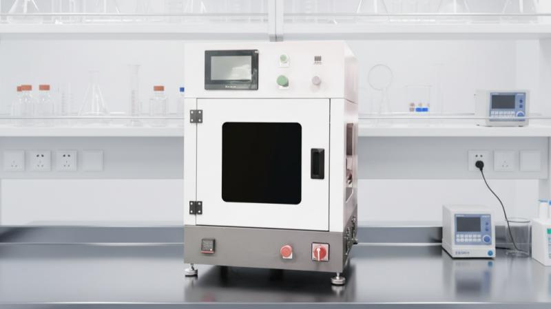
The ultrasonic coating equipment adapted for anode catalyst layer preparation possesses the following mass production characteristics:
1. Large Area Coating Capacity: Effective coating area up to 1.2m × 1.2m (customizable), supporting large-size MEA production;
2. High-Efficiency Mass Production Design: Equipped with 4 sets of ultrasonic nozzles or a reciprocating substrate conveying system, the spraying rate can reach 0.8m²/h. Based on 250cm²/MEA, the annual production capacity exceeds 120,000 pieces;
3. Fully Automated Control: Ultrasonic power, coating speed, slurry flow rate, and other parameters can be precisely adjusted to achieve 24/7 continuous production, ensuring batch consistency;
4. Multifunctional Adaptability: Compatible with anode catalyst slurries of different viscosities (from low-solids content slurries in the R&D stage to high-solids content slurries for mass production), while also supporting GDL hydrophilic/hydrophobic modification spraying (such as PTFE adhesive coating).
About Cheersonic
Cheersonic is the leading developer and manufacturer of ultrasonic coating systems for applying precise, thin film coatings to protect, strengthen or smooth surfaces on parts and components for the microelectronics/electronics, alternative energy, medical and industrial markets, including specialized glass applications in construction and automotive.
Our coating solutions are environmentally-friendly, efficient and highly reliable, and enable dramatic reductions in overspray, savings in raw material, water and energy usage and provide improved process repeatability, transfer efficiency, high uniformity and reduced emissions.
Chinese Website: Cheersonic Provides Professional Coating Solutions