
The Electrolyzer Scale‑Up Challenge
Core Engineering Challenges in Scaling Electrolyzer Technology from Laboratory to Gigawatt-Level Industrialization
As water electrolysis technology for hydrogen production transitions from laboratory-scale kilowatt prototypes to gigawatt (GW)-level industrial applications, the core challenges have shifted beyond scientific issues such as catalyst activity and membrane conductivity, and now center on systems engineering. It is necessary to bridge the “gap” between laboratory R&D and industrial manufacturing. The following analysis addresses four major engineering challenges and the pathways to successful scaling.
The Homogeneity Challenge: Achieving Consistency from “Handcraft” to “Industrial Product”
In the laboratory, researchers can fabricate high-performance membrane electrode assemblies (MEAs) with active areas of only a few to several tens of square centimeters. However, a GW‑scale electrolyzer requires tens of thousands of square meters of MEAs, composed of hundreds of thousands or even millions of repeating units, making consistency a critical issue.
1. Order‑of‑magnitude leap in batch‑to‑batch material consistency: The catalyst ink that is uniformly dispersed in a laboratory beaker must be processed in ton‑scale reactors, where variations in shear mixing fields, temperature gradients, and solvent evaporation kinetics can cause differences in particle size distribution and ionomer coating status, directly affecting the microstructure of the catalytic layer. The stable membranes used in the lab, when produced in kilometer‑long continuous manufacturing, must guarantee in‑plane and roll‑to‑roll consistency in thickness, ion exchange capacity, and mechanical strength. Micron‑scale defects or non‑uniformities can be amplified in series stacks, leading to localized overloading or gas crossover.
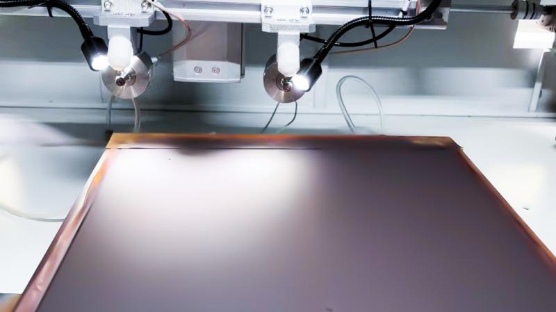
2. Precision and repeatability challenges in manufacturing processes: When coating processes are upgraded from manual doctor‑blading to high‑speed slot‑die coating at tens of meters per minute, slurry rheology and drying kinetics change fundamentally, and macroscopic defects such as edge effects, thickness fluctuations, and drying streaks become much more likely. Even minor non‑uniformities can accumulate into severe performance losses and safety hazards at GW scale. In assembly, laboratory single cells or short stacks can be uniformly compressed with precision fixtures, but a GW‑scale stack containing thousands of cells requires uniform pressure distribution across a compression plane several meters long. Slight pressure gradients can lead to uneven contact resistance, locally high current densities, and hot spots that accelerate degradation.
Scale Effects: Imbalance and Restructuring of Multi‑Physics Field Distributions
When stack size and power increase exponentially, the internal distribution of physical fields does not simply scale up but exhibits non‑linear changes and even disruptive restructuring.
1. The “weakest‑link” effect in current and voltage distributions: The total current of a GW‑scale stack reaches the giga‑ampere level and must be uniformly distributed across end plates of tens of square meters, then conducted through hundreds of thousands of bipolar plate pairs to each MEA. Improper end‑plate design or busbar layout can cause severe non‑uniformity in current density between the edges and the center. Millivolt‑level voltage differences between individual cells, when hundreds or thousands are connected in series, are amplified into considerable deviations. The system must tolerate the “bucket effect” rather than relying on the performance of the worst cell.
2. “Dead‑zone” risks in thermal management and fluid distribution: The waste heat power of a GW‑scale stack reaches hundreds of megawatts (comparable to a medium‑sized thermal power plant). When conventional cooling flow channels are scaled up, flow resistance and heat transfer efficiency change drastically, necessitating a tiered, zoned, and controllable cooling system to avoid local temperature differences exceeding 5 °C (which would significantly affect lifetime). Water or alkaline solution must be equally distributed among tens of thousands of parallel flow channels, while efficiently removing hydrogen and oxygen. After scaling up, the gas‑liquid two‑phase flow behavior within the channels becomes complex, easily causing gas locks or “dead zones” at electrode corners, leading to local reactant depletion and sharp concentration polarization.
3. Cumulative effects of mechanical stress and expansion: In a stack tens of meters long, thermal expansion of materials during thermal cycling accumulates into centimeter‑level dimensional changes. This expansion must be safely absorbed and released to avoid seal failure, structural deformation, or component cracking. For high‑pressure electrolyzer types, GW‑scale systems require massive pressure vessels or pressure‑resistant housings, whose design, fabrication, and inspection standards are entirely different from those of small laboratory containers, involving fatigue analysis, flaw tolerance, large‑scale welding, and other heavy equipment manufacturing challenges.
System Integration: The Complexity Leap from “Standalone Unit” to “Factory”
A GW‑scale electrolysis system is not merely an enlarged electrolyzer but a complex chemical plant, requiring the resolution of multi‑system coordination issues.
1. Mega‑system challenges in power electronics and grid interaction: GW‑scale rectification equipment must balance efficiency and reliability while mitigating harmonic pollution injected into the grid—issues that go beyond traditional electrochemistry. The system must couple with variable renewable energy sources and possess rapid power response capability from seconds to minutes, imposing extremely high demands on power supply control algorithms, stack dynamic performance, and auxiliary equipment coordination.
2. Reliability and efficiency trade‑offs in balance‑of‑plant (BOP): BOP energy consumption is key to project economics. Gas treatment equipment (compression, drying, purification) evolves from a laboratory “accessory” to a core energy‑consuming unit, requiring optimized selection and coupling with the main process (e.g., using stack waste heat to regenerate desiccants). The system consumes thousands of tons of ultrapure water per hour; water sourcing, recycling, and wastewater treatment become plant‑level issues that must be addressed, involving environmental assessments and substantial infrastructure development.
3. Hierarchical restructuring of control and safety systems: The control system must be upgraded from “direct control” of a single stack to an “intelligent distributed collaborative optimization” system, coordinating dozens of parallel stack modules, hundreds of large rotating machines, and thousands of sensing and control loops. Hydrogen throughput reaches the ton‑per‑hour level, and leakage risks escalate exponentially; safety systems must be designed to the highest process‑industry standards.
The “Impossible Triangle” of Reliability, Maintainability, and Cost
Investors’ core concerns center on long‑term reliability, ease of maintenance, and cost control—all three must be addressed synergistically.
1. The “distortion” problem in lifetime prediction: Thousands of hours of degradation data from the laboratory are difficult to extrapolate to the 80,000 hours (about 10 years) required for commercial operation. After scaling, degradation mechanisms may change due to non‑uniform physical fields. High‑fidelity lifetime prediction tools based on operational big data and physical models are needed to reduce investment risk.
2. The inevitability of modular design and online maintenance: A GW‑scale electrolyzer cannot be shut down for months due to failure of a single component. It must be designed as hundreds of standardized sub‑modules that can be independently isolated and replaced, while solving engineering problems such as online diagnostics, rapid isolation, and mechanical interface standardization.
3. The “learning curve” of manufacturing cost and supply chain security: The transition from manual/semi‑automatic to fully automatic production lines is central to cost reduction. Equipment design must consider manufacturability in advance, adapting to high‑speed, low‑cost mass‑production processes. A stable, high‑quality, low‑cost supply chain for key materials (e.g., membranes, catalysts, titanium plates) is a prerequisite for capacity release, avoiding external dependencies.
Core Pathways to Successful Scaling
1. Stepwise scaling with thorough validation: Follow the ladder of “laboratory → pilot (10–100 kW) → demonstration (MW‑scale) → commercial (10–100 MW modules) → GW‑scale plant.” At each level, address the corresponding scale‑specific core issues and accumulate data and experience.
2. Digitalization and simulation first: Use computational fluid dynamics, finite element analysis, system modeling, and other tools to complete most scale‑up design and optimization in a virtual environment, reducing trial‑and‑error costs.
3. Build an interdisciplinary team: Break down disciplinary silos, enabling electrochemists, mechanical engineers, control specialists, and plant designers to collaborate from the very beginning of the project.
A GW‑scale water electrolysis plant is essentially a highly integrated energy‑chemical combined facility. Overcoming its engineering challenges is not only about producing cheap green hydrogen, but also about reshaping modern industry’s ability to manufacture complex energy equipment on a large scale, with high efficiency, and through intelligent manufacturing. Ultimately, the winners will be those organizations that master complex systems engineering.
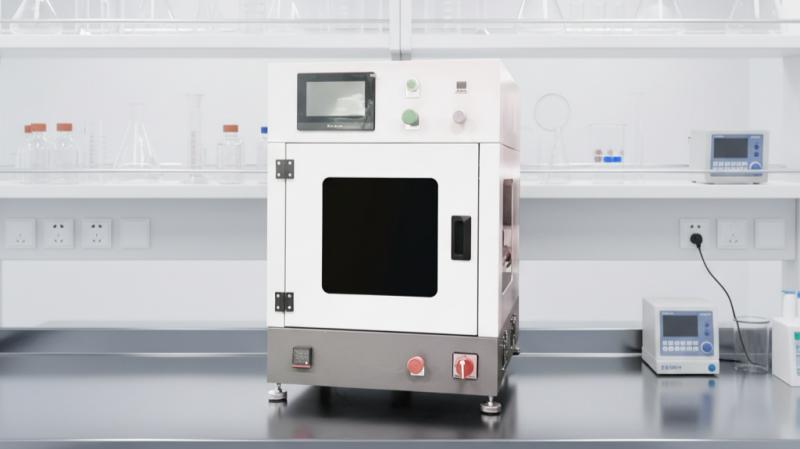
Ultrasonic Coating Technologies for Electrolyzers
Ultrasonic spray platforms deliver high-quality catalyst coatings and thin film layers for advanced electrolyzer manufacturing. Our ultrasonic coating systems apply controlled coating solutions onto electrolyzer substrates including electrodes, proton exchange membranes, gas diffusion layers (GDL), and other MEA-related components. With precise nozzle control and programmable flow rate, ultrasonic spray enables repeatable catalyst deposition using a catalyst deposition machine designed for material science-driven electrochemical performance in both bench top development and high-volume PEM electrolyzer production.
About Cheersonic
Cheersonic is the leading developer and manufacturer of ultrasonic coating systems for applying precise, thin film coatings to protect, strengthen or smooth surfaces on parts and components for the microelectronics/electronics, alternative energy, medical and industrial markets, including specialized glass applications in construction and automotive.
Our coating solutions are environmentally-friendly, efficient and highly reliable, and enable dramatic reductions in overspray, savings in raw material, water and energy usage and provide improved process repeatability, transfer efficiency, high uniformity and reduced emissions.
Chinese Website: Cheersonic Provides Professional Coating Solutions